gennaio 15, 2024
3176

The 3-wire AC dual capacitor wiring diagram plays a crucial role in the proper functioning of various electrical devices and motors. This configuration is commonly found in air conditioning units, HVAC systems, and other appliances that require the simultaneous operation of a fan and a hermetic compressor. In this article, we will delve into the components of the wiring diagram and provide a general guide for its implementation.
Common Terminal (C)
The common wire, usually labeled "C," connects to the common terminal on the capacitor.
The common terminal serves as a bridge between the fan and hermetic compressor circuits.
Fan Terminal (F)
The fan wire, labeled "F," is connected to the fan terminal on the capacitor.
This connection facilitates the electrical supply for the fan motor.
Hermetic Terminal (H)
The hermetic compressor wire, labeled "H," is connected to the hermetic terminal on the capacitor.
This connection ensures the proper operation of the hermetic compressor motor.
Follow these general steps for a typical 3-wire AC dual capacitor wiring:
Identification
Identify the common (C), fan (F), and hermetic compressor (H) wires.
Familiarize yourself with the capacitor terminals labeled for common (C), fan (F), and hermetic (H).
Connection
Connect the common wire (C) to the common terminal on the capacitor.
Connect the fan wire (F) to the fan terminal on the capacitor.
Connect the hermetic compressor wire (H) to the hermetic terminal on the capacitor.
Verification
Double-check the connections to ensure proper alignment.
Verify that the wiring matches the specifications outlined in the manufacturer's documentation.
Safety Precautions:
Always adhere to safety guidelines when working with electrical components.
Ensure that the power supply is disconnected before initiating any wiring work.
If uncertain about the wiring or any aspect of the installation, seek professional assistance.

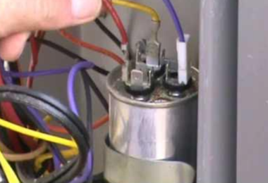
Dual Round HVAC Capacitor Wiring Diagram

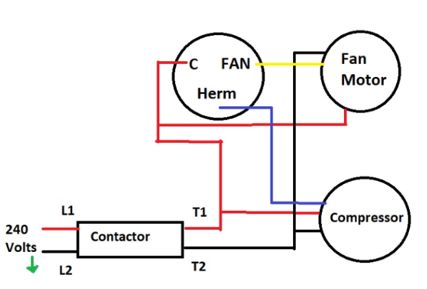
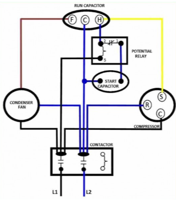
Wiring Diagram for AC Dual Capacitor

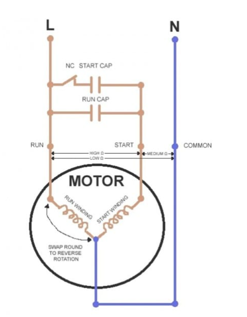
Compressor Capacitor Wiring Diagram
The 3-wire AC dual capacitor wiring diagram is a fundamental aspect of ensuring the efficient and reliable operation of electrical devices and motors. By understanding the components and following the prescribed wiring procedure, individuals can successfully implement this configuration in various applications. For specific equipment and capacitor models, it is crucial to refer to the manufacturer's documentation for accurate and detailed wiring diagrams.
Read More:
Capacitor Symbol in Circuit: A Roadmap for Electronics Enthusiasts